BTM-SG
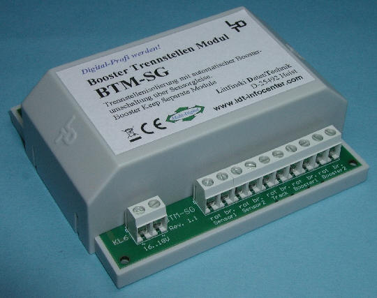
Booster Keep Separate Module for a secure electrical separation of Booster Current Circuits for all digital formats of the Digital-Professional-Series !

Each booster supplies current for an own rail section. The rail sections have to be isolated against each other by means of separation sections.
If a common layout ground will be used (digital pole “brown” or “J”) only one of the two digital poles will be isolated. At the 3-conductor track system will it be the center conductor which gets the supply from the digital pole “red”. At the 2-conductor track system will be only one of the two rails isolated at the separation section (digital pole “red” or “K”).
If a locomotive passes a separation section the electrical isolation will be temporary cancelled. At the 3-conductor track will this be caused by the sliding contact of the locomotive. At the 2-conductor track this will happen if the locomotive has more than one axle with sliding contact. A bypass of the separation section for a longer period will happen if the train stops on the separation section or contains conductive couplings and has sliding conductors at the train front and at the end.
During the electrical bypass of a separation section some balance current can flow over the loc and via the conductive couplings through the whole train. This can be enhanced if at the separation sections are tracks separated which gets supply from boosters of different brand. The amount of balance current flow will be affected by the different electrical properties of the boosters such as booster voltage and variances of the digital signal (e.g. edge steepness) but as well by different current load at the isolated track sections. The current flow can be influenced as well if one booster gets the supply from a model railway transformer and the other booster get the supply from a switching power supply.
Related to the level and duration of the balance current flow it can cause damage to the boosters, the locomotives, the conductive couplings and the rails.
The company Märklin offers for the 3-conductor track a separation rocker for the electrical isolation of the center conductor. This rocker works safely if a complete train with conductive couplings contains only one sliding contact for the current transfer. The disadvantage of the separation rocker is that the train has to pass the rocker with a minimum speed to prevent that train stops on the rocker.
The first approach to avoid high balance current during passing the separation section is using only boosters of one brand.
A comprehensive protection at the separation section can be achieved only by installing a complete isolation independently if a common layout ground has been installed or both digital poles at the separation section are separate isolated.
Features of the BTM-SG
The Solution:
- The Booster Keep Separation Module BTM-SG provides a secure electrical separation of the Booster Current Circuits.

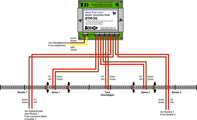
Wiring of the Booster Keep Separation Module BTM-SG for a 3 rail conductor system with complete current separation without common layout ground.

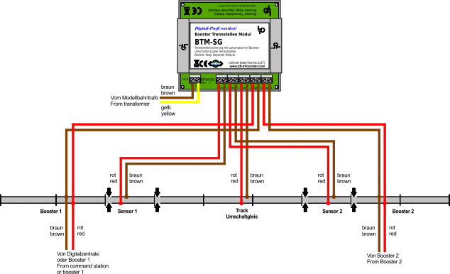
Wiring of the Booster Keep Separation Module BTM-SG for a 2 rail conductor system with complete current separation without common layout ground.
- With this wiring will get the switch-over track, which is situated between two booster current circuits as separation point, the digital current supply from one of the two boosters only. Corresponding to the driving direction will be the digital current supply to the Switch-Over track automatically switched to the competent booster circuit under the travelling train.
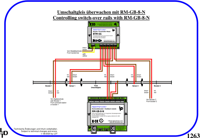
- The Booster Keep Separation Module BTM-SG will monitor the direction of a train between two isolated track sections. This isolated track sections are a so called Sensor-Track with an optimal length of 5 to 20 cm.
- Between the two Sensor-Tracks will be the Switch-Over track. This Switch-Over track has to have at least the length of the longest train on the layout.
- The Booster Keep Separation Module BTM-SG is able to switch a Digital Current of up to 8 Ampere.
- The Booster Keep Separation Module BTM-SG can operate without any problems on a layout in combination with any different boosters of various manufacturers and with various electrical characteristics.
- Components from the Digital-Professional-Series can operate on your digital layout without any problems.
- The finished module in a case comes with 24 month warranty.
- Each Booster Keep Separation Module BTM-SG comes with a detailed operating-instruction. Those instructions can be found within the next section.
- The Booster Keep Separation Module BTM-SG will be supplied as tested finished module in a case (-G). Suitable assembly material for the installation can be found under accessories.
Downloads
Instructions regarding this article can be found here: Downloads BTM-SG.
Instructions for all LDT-Components can be found here: Overview Downloads.
Sample-Connections
Sample-connections regarding this article can be found here: Sample-Connections BTM-SG.
Sample-connections for all LDT-Components can be found here: Overview Sample-Connections.

Add to Wish List / Prices
Attention: Products can only be added to the Wish List, if you are registered as customer at the LDT WebShop or if you are initially registered by interest of our products.
 | Add to Wish List: BTM-SG-G (Part-No.: 780503): Booster Keep Separation Module as a finished module in a case (55,90 €*). * All prices incl. VAT, plus Shipping. |
|---|


