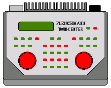
LDT-Decoder using on TWIN-CENTER!

 The TWIN-CENTER transmits the Fleischmann owned FMZ-Format as well as the standardized DCC-Format to the Lok- or accessory-decoder. This enables the control unit to respond to the LDT-Decoders for the DCC-Format (S-DEC-4-DC, SA-DEC-4-DC, M-DEC-DC and LS-DEC).

The TWIN-CENTER provides the s88-feedback bus for the feedback of events from the tracks. The LDT-Feedback Modules RM-88-N and RM-88-N-O (both for quick action switches) and RM-GB-8-N ((for track occupancy reports) as well as the Data-Switch DSW-88-N can communicate with the TWIN-CENTER without any problems.
At the data file twin-center_info_en you will find recommandations and sample connections for the TWIN-Center in communication with LDT-Components.
Recommandations for the installation of LDT-Decoder on TWIN-CENTER:
1. Registration of DCC Decoder on TWIN-CENTER
As per factory adjustment the TWIN-CENTER transmit FMZ-data to the decoder. To operate the LDT-Decoder the respective addresses have to be changed to DCC.
This operation is described within the TWIN-CENTER operating manual at paragraph 8.1 turnout/signals registered at the TWIN-CENTER on page 39.
Four statements have to be adjusted for each address:
- The so-called Virtual Address (from 1 to 2048). This complies e.g. to the number of turnouts.
- The Decoder Address or the decoder number. There are values of 1 up to 512 adjustable.
- At the decoder output values between 1 to 4 can be adjusted (as all LDT-Decoder contain four outputs).
- The Data Format. It has to be set to D for DCC, if the LDT-Decoder shall take over the switch events.
As the required adjustments at the TWIN-CENTER will cause probably at first some problems, we have created a table for your assistance including all details for the first 512 virtual addresses. Please load the file twin-center_address-table1 to your PC.
2. Programming the decoder address
During the operation at the TWIN-CENTER it can happen that after actuating the programming key the decoder will switch the turnout at output 1 immediately into a fast sequence such as it would confirm the programming of an address. In this case the address repetition storage of the TWIN-CENTER contains by error data on which the decoder is already reacting.
Proceed now as follows:
- Programming the decoder immediately after switching-on the command station, before any loc is travelling.
- Proceed with a RESET of the command station. All stored data will be preserved, only the address repetition storage will be deleted. On the TWIN-CENTER you have to activate at switched-on status the keys GO and STOP together until “reset” will be shown at the display.
3. Adjusting the switching times
The TWIN-CENTER output is not a clear DCC-data format but a mixture of FMZ and DCC format.
LDT-Decoder are optimal tuned to this data format. But will the decoder not switch always reliable it is possible to adapt the TWIN-CENTER to the requirement.
At the paragraph 8.5 Adjustment of switching time (page 42 of the TWIN-CENTER Operating Manual) this procedure is explained in detail. The factory adjustment has been set for the minimal and maximal switching time of 50ms.
Increase the minimum and maximum switching time in above case to 250ms.


